Automate ALS Forestry Analysis - Data Preparation
< Previous section Next section >
In this section of the ALS forestry guide, we will create a project configuration and a data preparation script for automation.
If you have not yet setup LIS Pro 3D for usage with Python (specifically the PySAGA api), please have a look at our Automation Guide and specifically the section Installation of LIS Pro 3D with Python. There, you will find a step-by-step description on how to setup your development environment!
It is recommended to complete the Automation Guide before proceeding with this section, in order to have more background knowledge about what we are doing here.
Folder Structure
Let’s assume our initial folder structure looks like this:
project # top-level folder
├── data
│   ├── 2716000_1241000.laz
│   └── 2716500_1241000.laz
└── scripts
We have a project folder called: project
ImportantIf you don’t have a project folder (i.e., a dedicated top-level folder) yet, create one!
NoteIn this project folder we will generate a set of subfolders later, where our scripts and processing results will be stored.
In the project folder, we have a data folder containing all our las/laz data
NoteThe data folder doesn’t need be in the project folder, it can also be at another location (especially, if it includes files of a whole country)
In the project folder, we have a scripts folder. All the Python scripts that we are writing will be stored here!
Later (when project_config.py was run/imported for the first time), we will create the following folder structure:
project # top-level folder
├── data
├── scripts
└── processing
    ├── grids
    │   ├── dtms
    │   ├── dsms
    │   ├── ndsms
    │   └── chms
    ├── shapes
    │   ├── aoi
    │   ├── tree_positions
    │   └── tree_outlines
    ├── point_clouds
    └── statistics
Open Visual Studio Code (VSCode)
From within VSCode, open the project folder (Menu: File > Open Folder or type Ctrl + K followed by Ctrl + O)
Create the Required Python Scripts
Create project_config.py, 01_data_preparation.py and 02_data_processing.py! In VSCode, open the explorer (left tab, top button) - this should show your project folder. Right click in the explorer panel and choose “New File…”.
project # top-level folder
├── data
├── scripts
|   ├── project_config.py
|   ├── 01_data_preparation.py
│   └── 02_data_processing.py
├── processing
└── ...Before executing any scripts, make sure to select the Python interpreter for execution that holds your LIS Pro 3D packages. This is crucial, otherwise you cannot run any LIS Pro 3D tools (see Automation Guide)!
If everything is set correctly, we can start scripting.
Fill the project_config.py
Copy the following code into your project_config.py script:
Use the upper-right button of the code block, in order to copy the whole code in one go!
import os
import sys

# make sure to adapt the SAGA_PATH if necessary!
os.environ["SAGA_PATH"] = (
    r"C:\Program Files\Laserdata\LIS Pro 3D"  # SAGA / LIS installation path
)
sys.path.insert(0, os.environ["SAGA_PATH"])

# -----------------------------------------------------------------------------
# processing directories
#
# the main folder of the project
BASE_DIR = r"C:\...\project"

# this folder should exist!
LAZ_DIR = os.path.join(BASE_DIR, "data")
# set LAZ_DIR to the folder of your las/laz data, if not within project folder!

## these folders have to be created
PROCESS_DIR = os.path.join(BASE_DIR, "processing")

GRIDS_DIR = os.path.join(PROCESS_DIR, "grids")
DTM_DIR = os.path.join(GRIDS_DIR, "dtms")
DSM_DIR = os.path.join(GRIDS_DIR, "dsms")
NDSM_DIR = os.path.join(GRIDS_DIR, "ndsms")
CHM_DIR = os.path.join(GRIDS_DIR, "chms")

SHAPES_DIR = os.path.join(PROCESS_DIR, "shapes")
AOI_DIR = os.path.join(SHAPES_DIR, "aoi")
TREE_POS_DIR = os.path.join(SHAPES_DIR, "tree_positions")
OUTLINES_POS_DIR = os.path.join(SHAPES_DIR, "tree_outlines")

PC_DIR = os.path.join(PROCESS_DIR, "point_clouds")
STATS_DIR = os.path.join(PROCESS_DIR, "statistics")
# -----------------------------------------------------------------------------

# -----------------------------------------------------------------------------
# create (non-existing) dirs
os.makedirs(PROCESS_DIR, exist_ok=True)
os.makedirs(SHAPES_DIR, exist_ok=True)
os.makedirs(GRIDS_DIR, exist_ok=True)
os.makedirs(PC_DIR, exist_ok=True)
os.makedirs(STATS_DIR, exist_ok=True)

os.makedirs(DTM_DIR, exist_ok=True)
os.makedirs(DSM_DIR, exist_ok=True)
os.makedirs(NDSM_DIR, exist_ok=True)
os.makedirs(CHM_DIR, exist_ok=True)
os.makedirs(AOI_DIR, exist_ok=True)
os.makedirs(TREE_POS_DIR, exist_ok=True)
os.makedirs(OUTLINES_POS_DIR, exist_ok=True)
# -----------------------------------------------------------------------------

# -----------------------------------------------------------------------------
# global settings: files, tool parameters, ...
AOI = os.path.join(AOI_DIR, "area-of-interest.shp")  # a manually drawn AOI
TILESHAPE_100 = os.path.join(AOI_DIR, "Tiles_100.shp")
LASVF = os.path.join(LAZ_DIR, "tiles.lasvf")

TILE_SIZE_PROCESSING = 100.0
OVERLAP = 20
Change BASE_DIR
This variable needs to point onto the project folder on your own machine: Replace this path ( here r"C:\...\project") with the actual path you are using (e.g., r"C:\path\to\forestry-als" or whereever the project resides):
# replace "data" here with the appropriate path!
BASE_DIR = r"C:\path\to\forestry-als"
Change LAZ_DIR (if necessary)
LAZ_DIR needs to point to the main folder of your data. If you follow along with the tutorial data of the Canton of Zurich, you can keep it as it is, but you need to change the path if the data folder is not part of the project folder.
# if laz files are elsewhere, completely replace "os.path. ..."
LAZ_DIR = os.path.join(BASE_DIR, "data")
Adapt Tiling for Processing
In this tutorial, we want to divide our AOI into small chunks of 100 x 100 m size for processing and add an overlap of 20 m. If you apply the processing workflow to your own dataset, you likely want to adapt the size and overlap to your needs.
Run Project Config
After this, run the project_config.py by using the run button in the upper-right corner of Visual Studio Code.
Define an Area of Interest
In the moment we still have no area of interest (AOI) defined. So let’s define one, using the GUI of LIS Pro 3D.
If you do not want to manually digitize your own area of interest, you can download the aoi-vector dataset shown below here. Make sure to download all parts of the shapefile (5 individual files). In that case, you can continue with section “Create 01_data_preparation.py …”.
Here you can also use an existing shapefile, e.g. a country or federal state boundary, if available!
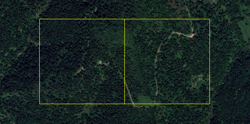
Open LIS Pro 3D and open the project from the previous tutorials. Here, we can see the outlines of the two point cloud files:
We first need to create a new shape layer that will hold our area of interest! Use the tool Create New Shapes Layer.
Tool: Create New Shapes Layer
Geoprocessing → Shapes → Construction // Tools → Shapes → Tools
| Parameter | Setting |
|---|---|
| Data Objects | |
| Shapes | |
| << Shapes | Shapes |
| Options | |
| Name | area-of-interest |
| Geometry Type | Polygon |
| Vertex Type | x, y |
| Number of Attributes | 2 |
| Attributes |
- Set its Name to area-of-interest
- Set its Geometry Type to Polygon
- Click Execute
A new area-of-interest polygon layer has been added to the Data tab.
This layer is still empty!
Digitize an Outline
Double-click on the area-of-interest in order to add it to the map (In the map you will not recognize any difference, as the layer is still empty!). Now digitize a shape.
Digitizing a shape is described in detail in our SAGA GIS Knowledge Base!.
Note that you can also run the Virtual > Create Tileshape from Virtual LAS/LAZ in order generate a shapes layer covering the whole area
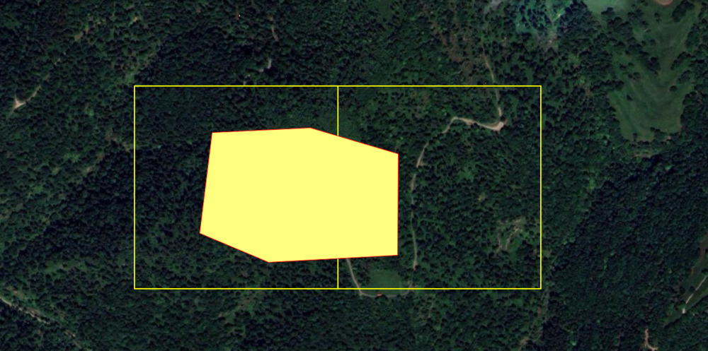
We will use the polygon shown here as an AOI - In order to follow the tutorial, the exact shape of the AOI is not crucial, just make sure it covers some of the data!
Set Spatial Reference for Layer
Tool: Set Coordinate Reference System
Geoprocessing → Projection // Tools → Projection → PROJ
| Parameter | Setting |
|---|---|
| Options | |
| Definition String | +proj=somerc +lat_0=46.95240555555556 +lon_0=7.439583333333333 +k_0=1 +x_0=2600000 +y_0=1200000 +ellps=bessel +towgs84=674.374,15.056,405.346,0,0,0,0 +units=m +no_defs |
| Display Definition as… | PROJ |
| Authority Code | 2056 |
| Authority | EPSG |
| Geographic Coordinate Systems | <select> |
| Projected Coordinate Systems | <select> |
| Well Known Text File | |
| Pick from Data Set | |
| Customize | |
| Data Objects | |
| Grids | |
| > Grids | No objects |
| Shapes | |
| > Shapes | 1 object (area-of-interest) |
- In the Authority Code section, fill in the EPSG Code 2056
- In the Shapes section, provide the area-of-interest shapefile we have just created
- Click Execute
Now the new shapefile has a projection that can be used within LIS Pro 3D correctly.
Save the AOI to Disk
Save the AOI dataset as “area-of-interest.shp” to the previously created folder in your project directory (C:\path\to\project\processing\shapes\aoi).
Leave the GUI open, because we will use it later again.
Create 01_data_preparation.py script
Overview of Tasks to be Performed
- Create a filelist
- Create LAS/LAZ Index
- Create a point cloud catalog (lasvf) for the available point clouds
- Create a tiling scheme of processing units with 100 m x 100 m size
- Select processing units that are covered by the AOI
- Save these selected units to disk (as
cfg.TILESHAPE_100)
Copy this code into your 01_data_preparation.py script!
import os
import project_config as cfg
from PySAGA import saga_api, lis_cmd
from PySAGA.tools import *


def prepare_data():
    # load aoi for processing_units creation
    AOI = saga_api.SG_Get_Data_Manager().Add_Shapes(cfg.AOI)
    if not AOI.is_Valid():
        return lis_cmd.Error_Return(f"Loading AOI {cfg.AOI} failed")

    # make list of all laz files
    inputfiles = lis_cmd.Create_File_List(
        cfg.LAZ_DIR,
        ".las;.laz",
        os.path.join(cfg.LAZ_DIR, "lasvf_input_file_list.txt"),
        True,
    )

    # create las-index
    if not lis_io.Create_LASLAZ_Index(
        FILES="",
        INPUT_FILE_LIST=inputfiles,
        INDEX_ALL=True,
        TILE_SIZE=0.000000,
        THRESHOLD=1000,
        MIN_POINTS=100000,
        MAX_INTERVALS=-20,
    ):
        return lis_cmd.Error_Return("Failed to execute tool")

    # create virtual las dataset
    if not lis_virtual.Create_Virtual_LASLAZ_Dataset(
        FILES="",
        INPUT_FILE_LIST=inputfiles,
        FILENAME=cfg.LASVF,
        METHOD_PATHS="relative",
        COLOR_DEPTH="16 bit",
    ):
        return lis_cmd.Error_Return("Failed to execute tool")

    # create processing_units
    processing_units = saga_api.SG_Get_Data_Manager().Add_Shapes()

    if not lis_tools.Create_Spatial_Processing_Units(
        SHP_EXTENT=AOI,
        SHP_UNITS=processing_units,
        TILE_SIZE=cfg.TILE_SIZE_PROCESSING,
    ):
        return lis_cmd.Error_Return("Failed to execute tool")

    # select relevant units
    if not shapes_tools.Select_by_Location(
        SHAPES=processing_units,
        LOCATIONS=AOI,
        CONDITION="intersect",
        METHOD="new selection",
    ):
        return lis_cmd.Error_Return("Failed to execute tool")

    # copy relevant units to new shapes layer
    selected_processing_units = saga_api.SG_Get_Data_Manager().Add_Shapes()

    if not shapes_tools.Copy_Selection_to_New_Shapes_Layer(
        INPUT=processing_units, OUTPUT=selected_processing_units
    ):
        return lis_cmd.Error_Return("Failed to execute tool")

    # save prepared processing_units
    selected_processing_units.Save(cfg.TILESHAPE_100)

    # free memory ressources
    saga_api.SG_Get_Data_Manager().Delete()

    return True


if __name__ == "__main__":
    # -----------------------------------------------------------------------------
    # start the logging

    starttime = lis_cmd.Start_Logging(False)

    # -----------------------------------------------------------------------------
    # call the processing function
    result = prepare_data()

    if not result:
        lis_cmd.Error_Exit("Processing task failed", starttime)

    # -----------------------------------------------------------------------------
    # stop logging
    lis_cmd.Stop_Logging(starttime)
Visually Inspect the Output
Let’s quickly validate that the AOI and selected Processing Units are aligned as expected. In the LIS Pro 3D GUI, open Tiles_100.shp and add it to the map. If you use the tutorial data, your output should roughly look like this (depending on how you have drawn your AOI):
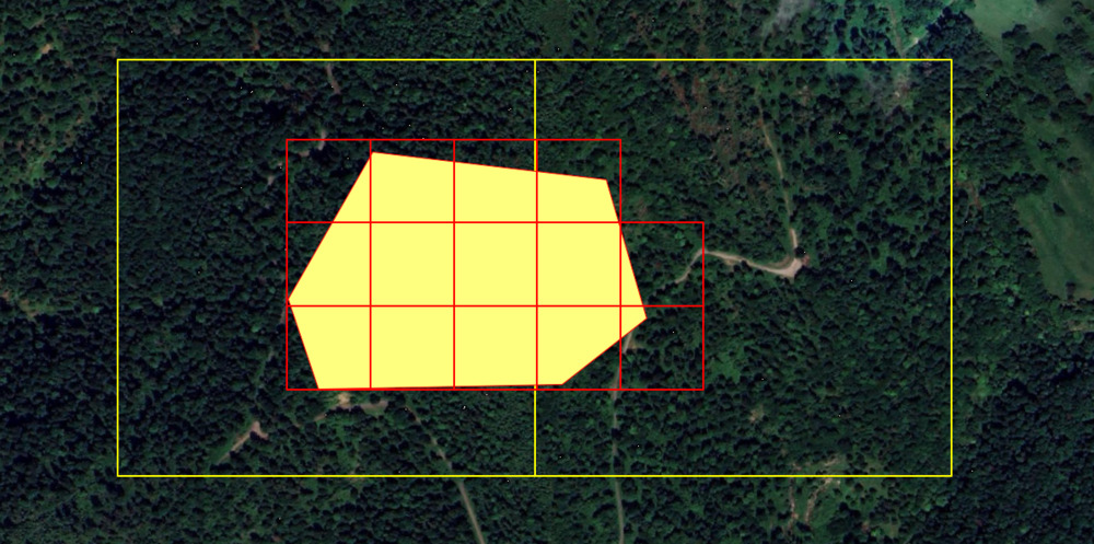
We can see that the AOI is fully covered by 100 x 100 m processing units (in red), hence everything is aligned correctly.
Recap
In this section of the tutorial, we have
- Created a project configuration that defines directories, filenames and tool parameters
- Created a data preparation script that
- Creates a filelist
- Creates LAS/LAZ Index
- Creates a point cloud catalog (lasvf) for the available point clouds
- Creates a tiling scheme for processing units with 100 m x 100 m size
- Selects processing units that are covered by the AOI
- Saves these selected units to disk (as
cfg.TILESHAPE_100)