Derivation of DTM, DSM and nDSM
Digital terrain and surface models are among the most fundamental datasets to be derived from point cloud data. Luckily, LIS Pro 3D facilitates this process with dedicated tools!
Prerequisite
The derivation of a digital terrain model (DTM) requires a point cloud that has been classified into ground points and other (non-ground) points.
If your point cloud is not yet classified into ground and non-ground points, you can follow our tutorial on ground classification here!
Test Dataset
You can follow the next steps with a point cloud test dataset (2684500_1247000.laz) which you can download here. This data is orignally provided by the Canton of Zurich as Open Government Data.
Point Cloud Import
We first start by importing the laz-file:
Tool: Import LAS/LAZ Files
Geoprocessing → LIS Pro 3D → Import/Export → LAS/LAZ // Tools → LIS Pro 3D → Import/Export
| Parameter | Setting |
|---|---|
| Options | |
| Input Files | C:\\…\2684500_1247000.laz |
| Attributes to import besides x,y,z … | |
| GPS-time | ☐ |
| Number of the return | ☐ |
| Number of returns of given pulse | ☐ |
| Intensity | ☐ |
| Classification | 🗹 |
| … | … |
- Provide the laz-file as input
- Tick the box for importing the classification
- Click Execute
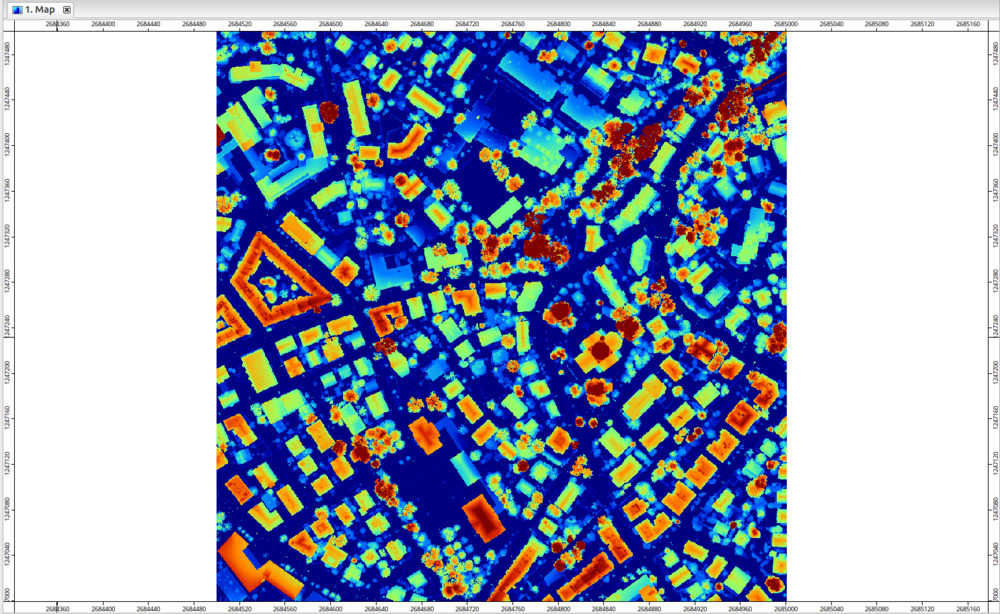
The resulting data point should look like this, when added to a map view:
Create a DTM From Point Cloud Data
In its simplest form, we can create a DTM by taking the mean of all ground points that fall into a grid cell using the following tool:
Tool: Point Cloud to Grid
Geoprocessing → LIS Pro 3D → Conversion → From Point Cloud // Tools → LIS Pro 3D → Conversion
| Parameter | Setting |
|---|---|
| Data Objects | |
| Point Clouds | |
| >> Point Cloud | 2684500_1247000 |
| Attribute | Z |
| Filter Attribute | classification |
| Options | |
| Aggregation | mean |
| Attribute Filter | ☐ |
| Elevation Filter | ☐ |
| Search Radius | ☐ |
| Filter Attribute Min / Max | 2;2 |
| Target Grid System | user defined |
| Cellsize | 0.5 |
| West | 2.6845e+06 |
| East | 2.685e+06 |
| South | 1.247e+06 |
| North | 1.2475e+06 |
| Columns | 1001 |
| Rows | 1001 |
| Rounding | 🗹 |
| Fit | cells |
- Provide the point cloud file as input
- Select mean as the Aggregation operation
- Check Filter Attribute and make sure Filter Attribute Min / Max is set to 2;2
- Click Execute
The tool will generate a new raster named Aggregate_Z_mean. Let’s rename this dataset to DTM to reflect the content of the dataset.
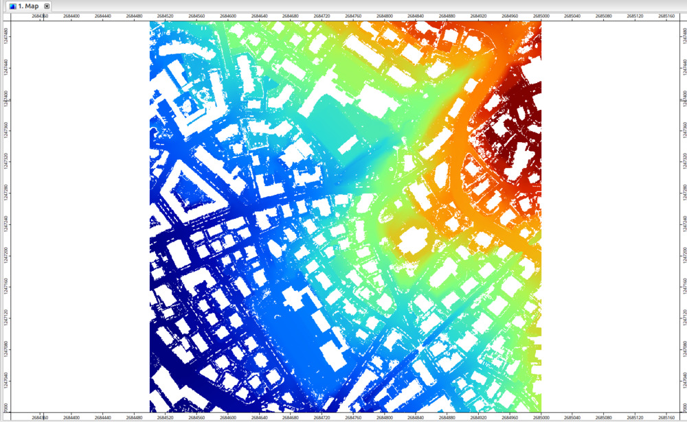
Add the DTM to the map and remove the point cloud from the map view for a moment (this would hide certain details!). You should now see the DTM. Below buildings, there are no ground points, hence we still have holes in the DTM:
Close Gaps in DTM
Now we still have gaps in our DTM. For many applications however, we need a continuous, gap-free DTM. This can be achieved by closing the gaps:
Tool: Close Gaps
Geoprocessing → Grid → Gaps // Tools → Grid → Tools
| Parameter | Setting |
|---|---|
| Data Objects | |
| Grids | |
| Grid System | 0.5; 1001x, 1001y; 2684500…x 1247000…y |
| >> Grid | DTM |
| > Mask | <not set> |
| < Changed Grid | <not set> |
| Options | |
| Tension Threshold | 0.1 |
- Provide the Grid System
- Provide the dataset DTM in the Grid section
- Click Execute
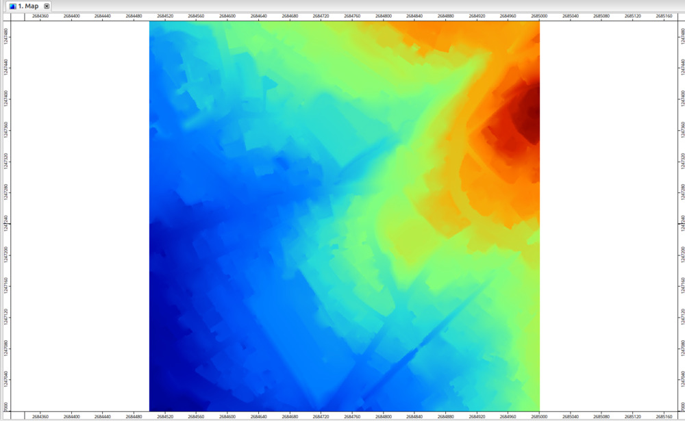
This will close remaining gaps in our DTM. With the current setting, the gaps will be closed in the existing layer. The resulting DTM without gaps should look similar to this:
Create DSM From Point Cloud Data
For many applications and visualization purposes, it is nice to have a digital surface model (DSM) that contains all object on the surface (buildings, vegetation, …) and not just the ground. This can be achieved with the same tool, but slightly tweaked settings:
Tool: Point Cloud to Grid Geoprocessing → LIS Pro 3D → Conversion → From Point Cloud // Tools → LIS Pro 3D → Conversion
| Parameter | Setting |
|---|---|
| Data Objects | |
| Point Clouds | |
| >> Point Cloud | 2684500_1247000 |
| Attribute | Z |
| Filter Attribute | <not set> |
| Options | |
| Aggregation | max |
| Attribute Filter | ☐ |
| Elevation Filter | ☐ |
| Search Radius | ☐ |
| Target Grid System | grid or grid system |
| Grid System | 0.5; 1001x, 1001y; 2684500…x 1247000…y |
| << Target Grid | <create> |
- Provide the point cloud as input
- Set the Attribute to Z
- Set the Aggregation to max (highest point/z-value per cell)
- Set the existing grid as the target grid
- Click Execute
The output will initially be named Aggregate_Z_max. Let’s rename it to DSM to reflect the content. Add it to the map view and disable the other layers:
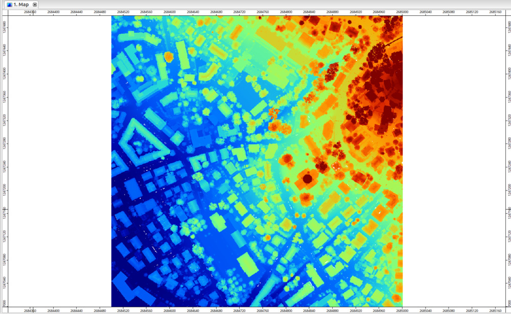
Note: just like the initial version of the DTM, the DSM also still has gaps due to cells without points. Therefore, we will also run Close Gaps on the DSM:
Tool: Close Gaps
Geoprocessing → Grid → Gaps // Tools → Grid → Tools
| Parameter | Setting |
|---|---|
| Data Objects | |
| Grids | |
| Grid System | 0.5; 1001x, 1001y; 2684500…x 1247000…y |
| >> Grid | DSM |
| > Mask | <not set> |
| < Changed Grid | <not set> |
| Options | |
| Tension Threshold | 0.1 |
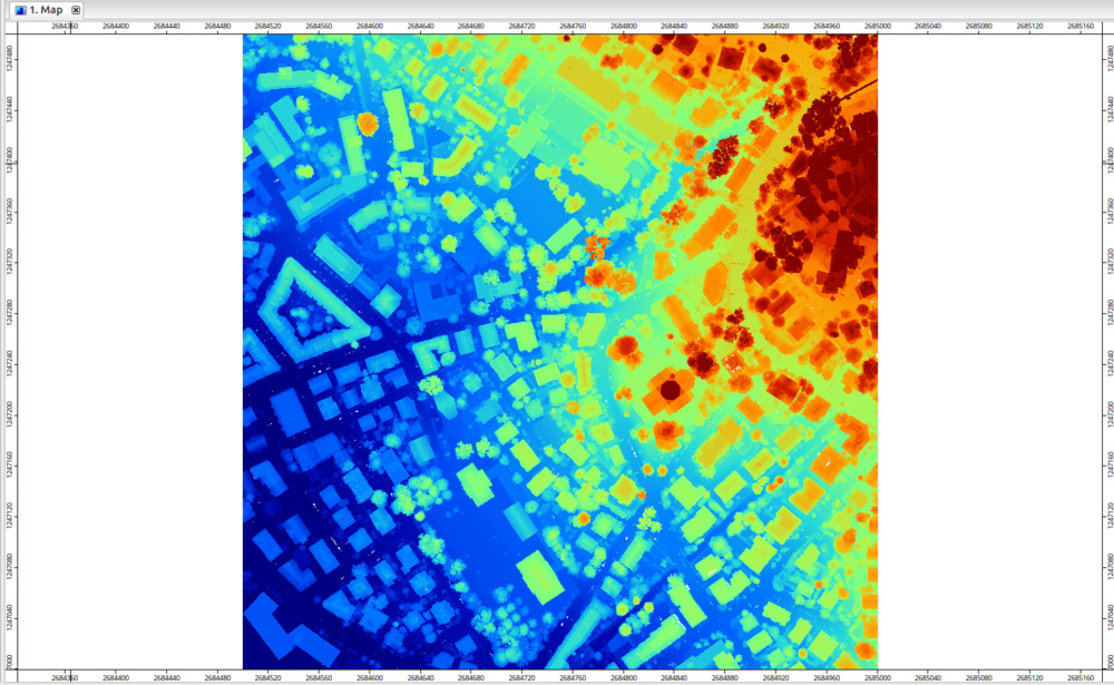
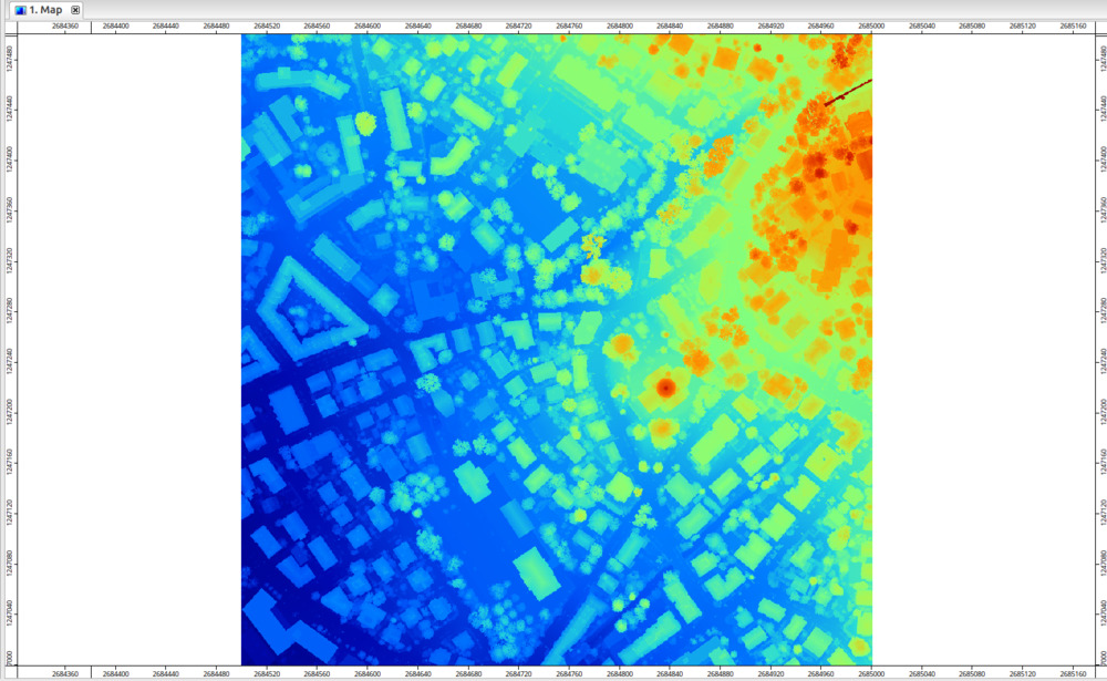
The resulting layer no longer has any areas with missing data:
LIS Pro 3D includes a dedicated tool for generating gridded derivatives directly from virtual LAS/LAZ files (LIS Pro 3D > Virtual > Get Grid from Virtual LAS/LAZ). This approach eliminates the need for prior point cloud import and allows seamless raster generation from the underlying point cloud catalog without consideration of the physical tiling of the point cloud dataset on disk.
Normalized DSM - Height Above Ground
Some applications (i.e., estimating tree height or segmentation of tree crowns) benefit from the use of a normalize Digital Surface Model (nDSM) which simply contains the height above ground. LIS Pro 3D offers a dedicated tool to compute a nDSM:
Tool: Create nDSM Geoprocessing → LIS Pro 3D → Arithmetic → Grid // Tools → LIS Pro 3D → Arithmetic
| Parameter | Setting |
|---|---|
| Data Objects | |
| Grids | |
| Grid System | 0.5; 1001x, 1001y; 2684500…x 1247000…y |
| >> DSM | DSM |
| >> DTM | DTM |
| << nDSM | <create> |
| Options | |
| Negative Values | set to zero |
- Provide both the DTM and the DSM as input datasets
- We recommend to choose set to zero for Negative Values. This will eliminate processing anomalies that can occur when closing gaps in the raster models
The result should look similar to the following: